psuctl🔌: a tiny Desktop PSU controller for Raspberry Pi
Published:
This is psuctl🔌; a small desktop Power Supply Unit (PSU) controller for a Raspberry Pi built around an ATtiny85. The goal is simple: make the Pi power on/off in a controlled way, and make the whole setup reliable enough that you can forget it exists.
I originally built the first version with a Pi Pico 2W, because it’s convenient and fast to iterate on. But in practice it was too clever for this job: every now and then the Pico would get corrupted and I’d end up reprogramming it. That’s fine when you’re prototyping, but it’s the opposite of what you want in a power controller.
So I switched to the ATtiny85, and it’s been boring ever since ; which is exactly the point.
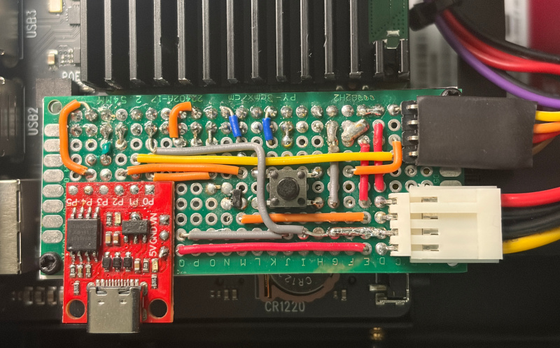
psuctl🔌 on my Homelab setup controlling a server grade power supply
The basic idea
A Raspberry Pi shouldn’t just have power yanked from it if you care about EMMC/SD cards, filesystems, or sanity. So in order to turn the Pi off safely from a button. However if you are trying to use a traditional PSU, we first have to ask Linux to shut down. However after shut down is complete, we have to manually unplug the PSU from the wall; which I wanted to automate such that we have with other traditional desktop computers. And in order to do that, we need a small controller sitting between the Pi and the PSU that can:
- Tell the Pi to shut down (politely, via a GPIO line).
- Watch whether the Pi is still alive (another GPIO line).
- Cut power only after the Pi is actually down (so the filesystem has time to finish).
That’s what the ATtiny85 is doing here: it’s basically a tiny supervisor that speaks “GPIO” to the Pi and “power” to the PSU.
Wiring notes
The wiring is straightforward: the ATtiny85 connects to the Pi via a couple of GPIO lines, and it also sits in the path that controls power from the PSU.
One important practical detail: don’t starve the Pi of current.
In order for the PSU to deliver enough current to the Raspberry Pi reliably, we have to use multiple 5V and GND connections between the PSU and the Pi. It’s not just about voltage; it’s also about reducing resistance and keeping the wires/connectors from becoming the bottleneck.
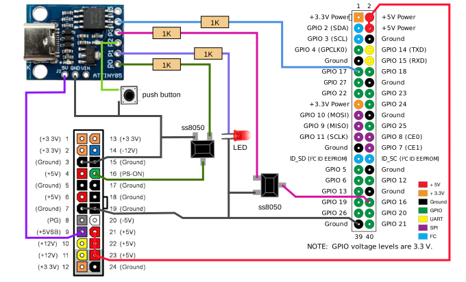
Connections between the ATtiny85, Raspberry Pi, and PSU
Programming the ATtiny85 over USB Type-C
This part worked, but it definitely took the most “digging”.
The main headache was Micronucleus. On Apple Silicon (and with newer Arduino IDE versions), support is… let’s say “not great.” So in order to actually upload code without fighting the toolchain every day, I ended up setting the environment up manually.
Here’s what worked for me:
- Install Digistump board definitions: In order for the Arduino IDE to even know what these boards are, we have to add the Digistump package index and install the board support package. Add this JSON URL to Arduino Board Manager URLs, then install
Digistump AVR Boards:https://raw.githubusercontent.com/digistump/arduino-boards-index/master/package_digistump_index.json - Manually install ATTinyCore: In order to get proper ATtiny support (especially when the default path is messy), we have to bring in ATTinyCore ourselves.
- Download ATTinyCore from the releases of the repository
- Extract it
- Copy it into the
hardwarefolder inside your Arduino project directory
- Flash the firmware over USB-C: Once the board support is in place, you can program the chip normally.
- Copy the contents of
controller.inoto your project main file. - Select the boards in Arduiono IDE to
ATtiny85 w/Micronucleus (Digispark) - Click complile and upload, wait until uploading message on the Arduiono terminal and plug the ATtiny85 via USB-C; wait until it shows
Micronucleus done. On board led should blink in a pattern at this point.
- Copy the contents of
At that point, the controller becomes “set and forget,” which is the whole reason for using an ATtiny in the first place.
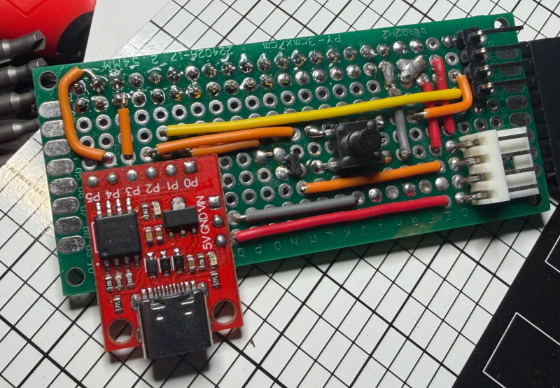
Work-in progress controller
Raspberry Pi side configuration
The Pi needs to understand two things:
- The ATtiny can request a shutdown by pulling a GPIO line low.
- The Pi can signal I’m alive / I’m shutting down via another GPIO.
In order to make the Pi respond to that request automatically, we have to add the overlays in /boot/firmware/config.txt:
# ATtiny pulls GPIO16 low to request shutdown
dtoverlay=gpio-shutdown,gpio_pin=16,active_low=1,gpio_pull=up
# GPIO26 indicates Pi running status
dtoverlay=gpio-poweroff,gpiopin=17,active_low=1
Once this is set, the Pi treats that GPIO shutdown line like a real “power button” request. That means the controller can ask for a clean shutdown, then wait until the Pi is actually down before cutting power.
At first, I added a 10-second delay after the first “Pi is going down” detection and then checked the running-status line. That worked fine for normal shutdowns, but it had an annoying edge case: during a reboot, the Pi can briefly look “down” before it comes back, and the controller would sometimes cut power right in the middle of that restart.
To make it safer for both shutdowns and reboots, I increased the delay to one minute. It’s a bit more conservative, but it avoids killing the Pi during a reboot cycle.
Conclusion
At the end, reliability matters in this kind of application. The Pico is great, but it’s still a fairly complex device with a lot going on. For something that’s effectively part of your power infrastructure, complexity is a risk. The ATtiny85 does less, but it does it consistently. And in order to build a dependable power controller, that’s exactly what we want: small firmware, simple logic, minimal surprises.