Project Evie: Electric Vacuum Pump Conversion
Published:
In this episode I am documenting the process of retrofitting an electric vacuum pump for camshaft-driven vacuum pumps in LTG engines. LTG is the forced-induction version of the GM ECOTEC engine family, which was used in many GM models in traditional rear-wheel-drive configurations such as the Cadillac ATS and LTG Camaro. Naturally aspirated versions of this engine were also used in several other configurations as well. 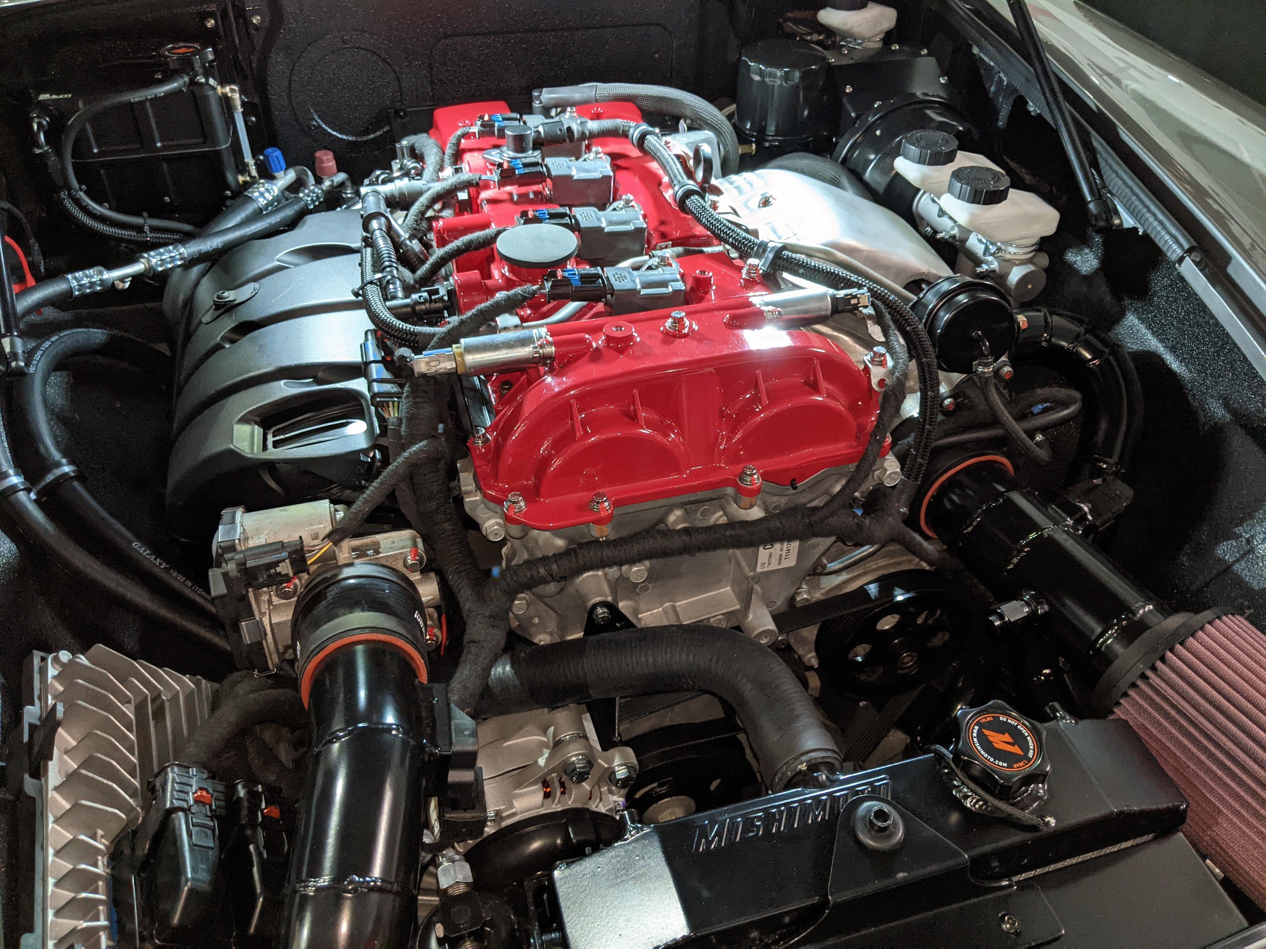 If you do some research about the LTG version of this engine, you will quickly find that it is an extremely versatile engine and has a lot of potential to make power. Being a turbo charged four-cylinder engine, it is surprisingly good on gas mileage as well with respect to the power it puts out. This engine is also very compact, making it a very good candidate for tight applications.
However, there is a small issue with how it was designed to fit a camshaft-driven vacuum pump. If this pump fails, it can send debris throughout the internals of the engine, potentially destroying it completely. In this post, I will discuss this issue in a bit more detail based on my research and describe a solution to mitigate the problem by converting the camshaft-driven mechanical pump to a GM electrical vacuum pump inspired by some of the other projects in the community.
Disclaimer: This is not a guide; it is a documentation of the process that I followed in order to mitigate this issue. While I did my research on all of the components and their suitability for this application, the quality of the assembly may affect the reliability of the system. If you attempt to follow any of these steps, please do so at your own risk. I am not liable for any damage that may occur as a result of following any part of this documentation.
How the Brake Booster Works
Before looking at the problem, let’s start with how the vehicle brake system works. Modern vehicle brake systems are based on hydraulic pressure. In simple terms, when you apply the brake pedal, it pushes fluid through brake lines and squeezes the brake pads against the rotors. However, almost all modern vehicles add brake assist to improve braking responsiveness and make the pedal lighter to press. Our engines naturally act as large vacuum pumps that pull air into the cylinders before combustion. Automakers traditionally used this naturally created vacuum to power various components in cars, including brake boosters and other actuators.
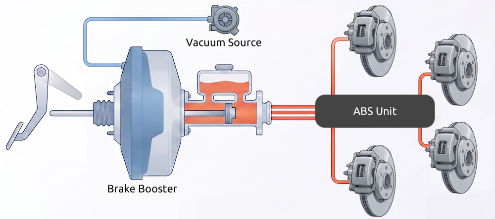
AI Generated Illustration : credits to NotebookLM
With forced induction systems such as turbochargers and superchargers, this vacuum is no longer consistent because the intake manifold can become pressurized under boost. This created a problem, requiring separate vacuum pumps to maintain a stable vacuum supply for the brake booster. The brake booster itself consists of a large diaphragm mounted between the brake pedal and the master cylinder. Under normal conditions, vacuum is applied to both sides of the diaphragm. When the brake pedal is pressed, atmospheric pressure is allowed into one side of the booster while vacuum is maintained on the other side, creating a pressure difference that assists the driver’s input. Without this assistance, significantly more pedal force would be required to stop the vehicle.
Issue with the Camshaft-Driven Pump
Since the LTG engine is turbo charged, it cannot rely solely on intake manifold vacuum because the turbocharger frequently places the intake system under positive pressure. To solve this, GM equipped the engine with a mechanical vacuum pump driven directly by the exhaust camshaft. Although the design works well for the most part, there are a well-documented number of cases where the vacuum pump has become a known failure point in the LTG community. If you do a Google search for the terms GM Cadillac LTG vacuum pump failure, you will find many documented cases describing this issue.
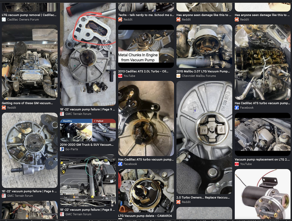
This particular pump does not use conventional bearings. Instead, the rotating assembly rides on a thin film of engine oil, while a vane sweeps along the inner wall of the pump to create vacuum. This vane is made from a composite material and uses rubber sealing strips on its edges.
Since the vacuum pump is driven directly by the camshaft, its rotational speed is proportional to the engine speed. For example, at 4000 RPM engine speed, the pump itself is already spinning at several thousand RPM, which introduces a significant amount of wear over time. Based on information available online, the composite vane material appears to be the first component to fail. Once damaged, debris can obstruct the rotation of the pump shaft. When this happens, the coupling that connects the pump to the camshaft can fail catastrophically and break apart inside the top end of the engine. The resulting metal debris may then circulate throughout the engine through the lubrication system, potentially causing severe engine damage.
Another drawback of the mechanical pump is that it continuously consumes a small amount of engine power because it is always driven by the camshaft, regardless of whether additional vacuum is needed. Because of these concerns, many enthusiasts have started exploring alternatives that remove the mechanical pump entirely and replace it with an electrically driven vacuum pump.
Background and Motivation
When I was doing my research on these pumps, I came across an amazing thread by terrainray on the terrainforum. They did a pretty good job documenting the entire conversion, including the components, wiring, and testing results. This thread became the main motivation for me to continue my research and further improve the system while using OEM parts as much as possible.
During this research, I also found that GM appears to have moved away from the mechanical vacuum pump design. Most vehicles that originally used the camshaft-driven pump were updated to use electrical vacuum pumps in the 2023 model year and later.
Planning
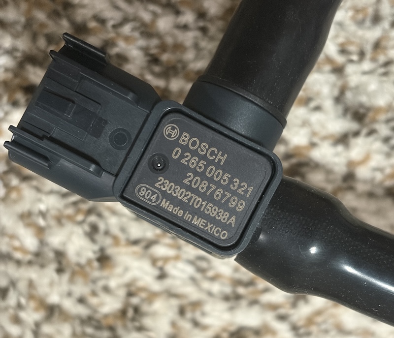
I wanted the entire system to look identical to the existing components under the hood. This meant using similar wiring harnesses, vacuum lines, fuse boxes, pumps, mounting hardware, and sensors. The original vacuum sensor in this system is GM Part #20876799 (ACDelco Part #20876799). This sensor was manufactured by Bosch and also includes an internal one-way valve. After a bit of research and experimentation, I found that this is a 5 V sensor that outputs an analog signal between 0 V and 5 V corresponding to the measured vacuum pressure. I wanted to use the same sensor in my setup since it is readily available and, being an OEM part, reliability is not really a concern. I couldn’t find the exact part number for the connector to this sensor, however it fits exactly to the H13 3 pin headlight connector. I used the 68064997AA part number connector with a slight modification to the housing.
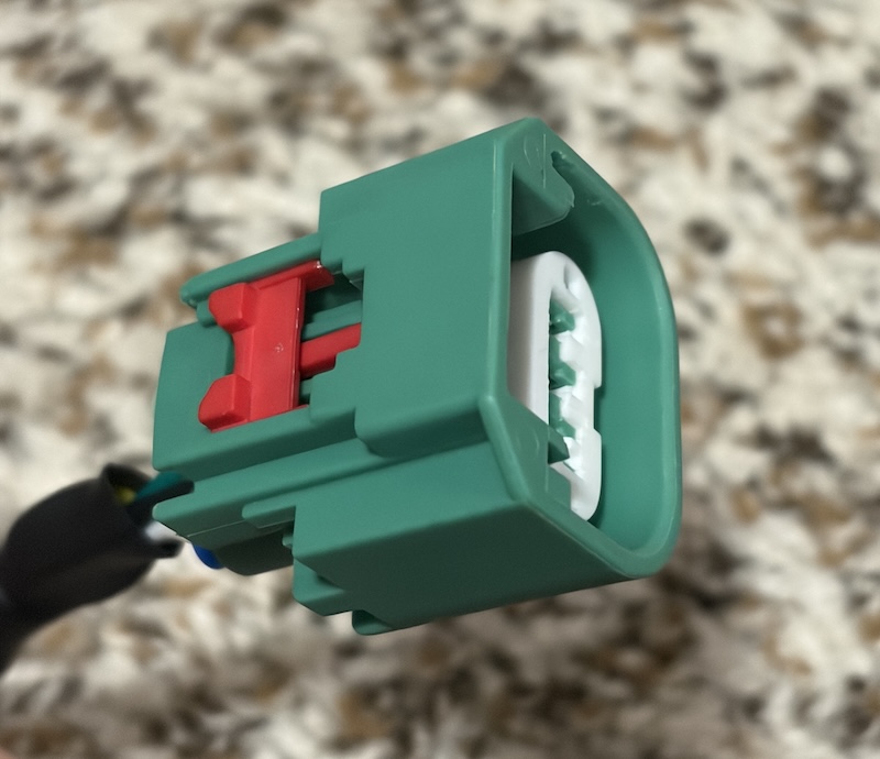
Next, I started looking at the available vacuum pump options. Based on my research, I found that GM uses pumps manufactured by Hella, with several different variants available. I was particularly interested in the pump used in the C7 Corvette, the UP30 (OEM #23451913), and the pump used in the 2023 Traverse, the UP5.0 (OEM #84491774), which is the most powerful variant. After bench-testing both pumps using the OEM sensor and a prototype ATtiny85 microcontroller setup, I measured the time required to reach -22 inHg of vacuum, which is approximately the idle vacuum level produced by the mechanical pump. I also compared the noise level and power consumption of each option and eventually decided to go with the UP5.0.
The next step was planning the installation under the hood. I had to determine possible mounting locations for the pump, controller, and fuse box, as well as figure out how to route the vacuum lines. This entire process took months, mainly because Saturdays were usually the only time I had available to work on the project.
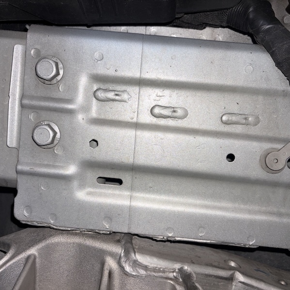
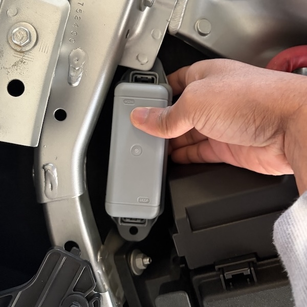
After finalizing everything, I found that the ideal location for the pump was on the passenger-side frame rail, right under the fuse box. Conveniently, GM had already left two mounting holes there that I could reuse for the installation. For the fuse box, I chose to mount it right next to the OEM fuse box.
Design a Controller
Unlike the stock mechanical pump, an electrical vacuum pump cannot simply be connected directly to the vehicle power system. We need a controller to continuously monitor the vacuum sensor, decide when the pump should turn on and off, and protect the electronics from the harsh automotive environment. Running the pump continuously is also undesirable, as it increases noise, power consumption, and wear. Therefore, the controller implements hysteresis to maintain the vacuum within a target range while avoiding excessive on-off cycling of the pump.
After bench-testing the entire setup with an ATtiny85 MCU, I wanted to build an automotive-grade controller. This means that all the electronic components used in this project should be able to withstand the harsh, noisy under-the-hood environment. The closest automotive-rated MCU I found for this application was the ATtiny412-SSNR. Since both the ATtiny412 MCU and the BOSCH sensor operate at 5 V, we need to regulate the 12 V supply efficiently. In particular, using a simple LDO regulator in this setup is not ideal due to the power dissipation. Instead, I settled on the TSR 1-2450E system-on-package buck converter. To drive the pump, I selected the VN5T016AHTR-E, an active-high 43 A high-side switch in the HPAK-7 package from ST. In addition to these major components, I added protection circuitry on both the signal and power lines to make the system tolerate the electromagnetic noise typically found under the hood. All of these components are automotive grade.
Based on these parts, I created the final schematics using KiCad. You can find the source files related to the controller here. The next step was to write the control logic and program the ATtiny412. I modified my bench-testing code so that it properly handles hysteresis; you can find the Arduino code here. To program the ATtiny412, we need a UPDI (Unified Program and Debug Interface) programmer. This is a single-wire programming interface that connects directly to the J1 header on the PCB and can be programmed from the Arduino IDE.
Technically, we can drive the pump directly from the MOSFET since it supports up to 43 A. However, I did not want to do that for a couple of reasons. The first reason is redundancy. Although I built multiple copies of the controller and keep spare units in my glove box, I still wanted an easy fallback method to turn on the pump. The second reason is that I did not want to pull an additional 15 A through the fuse-box accessory line. Therefore, I decided to use a second mini relay. In a situation where we do not have access to a controller, the controller socket can simply be bypassed with a jumper wire by connecting the vehicle’s 12 V accessory line to the controller output. This causes the pump to turn on whenever the vehicle is in accessory mode, which behaves similarly to the stock mechanical pump.
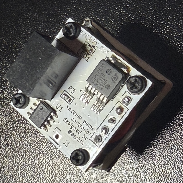
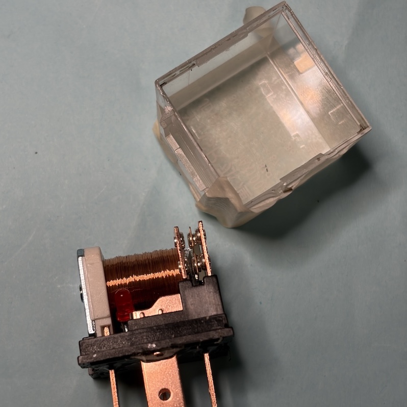
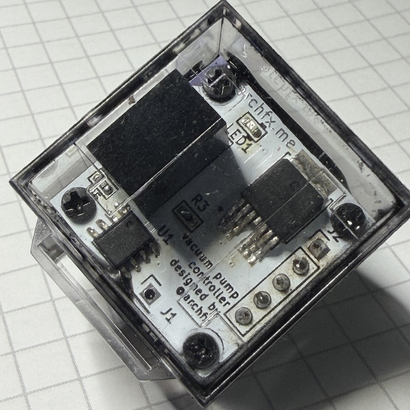
When I started the controller design, I wanted the controller to plug directly into the relay and fuse box. To make things easier, I decided to use a standard 5-pin mini-relay enclosure; unfortunately, standalone relay enclosures are not readily available for purchase. Therefore, I bought a few inexpensive transparent 5-pin mini relays, carefully removed their internal components, and installed the controller inside the empty housing. This allows the relay and fuse box to interface directly with the controller.
Electrical Wiring
After the controller was assembled, I wanted to find a good automotive fuse box that could accommodate two mini relays. I was able to find a modular fuse-box assembly kit from the MTA Gray Modules catalog. As the base, I used the part number MTA 0301504. Based on the documentation, it was straightforward to identify the rest of the components compatible with this enclosure, and everything simply snaps into place. For the electrical connections, I used 12 AWG silicone wire for the vacuum pump, which requires approximately 15 A on average, and 20 AWG silicone wire for the remaining connections, which require less than 2 A on average.
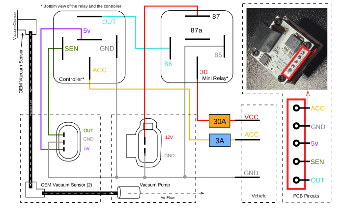
Schematics of the Electrical and Vacuum Circuits
I then assembled everything according to the schematic shown above. For both the ACC (switched power) and constant 12 V lines, I used inline fuses rated at 3 A and 30 A, respectively. All exposed wiring, such as the sensor connections and the main power lines for the pump, was protected using automotive wiring harness wrap. For the constant 12 V connection, I used a 6 mm ring terminal with proper heat shrink and connected it to the live distribution bus bar located outside the engine-bay fuse box. For the ACC line, I used a fuse tap and routed it to one of the internal switched fuses; in my case, I used F43. To avoid the wire being squeezed by the fuse-box cover, you can release the locking lever that lifts the entire fuse assembly. This allows the wire to be routed underneath and passed through one of the existing openings into the fuse-box compartment. A list of components and connectors used during the assembling process can be found here.
Under-the-Hood Mounting
After taking some measurements from the mounting locations, I designed the brackets required for mounting the pump and relay-fuse box using FreeCAD. After several prototypes, it became obvious that 2 mm stainless-steel sheet metal was the best choice for both mounts. During the design process, I made sure that the pump sat as close as possible to the 90-degree bend in the bracket so that the forces acting on the fulcrum would be minimized. There is also very little space available in this area, so the design had to be fairly compact.
The stock holes that GM left for mounting the pump are 7 mm. However, I wanted to install M6 rivet nuts, which require 9 mm through holes. Therefore, I enlarged the holes with a 9 mm drill bit and applied a healthy amount of touch-up paint before installing the rivet nuts. After the paint had dried, I installed stainless-steel rivet nuts into the mounting holes. Since there was not enough space to use the proper installation tool, I had to resort to the old-school ratchet-and-wrench technique to install them.
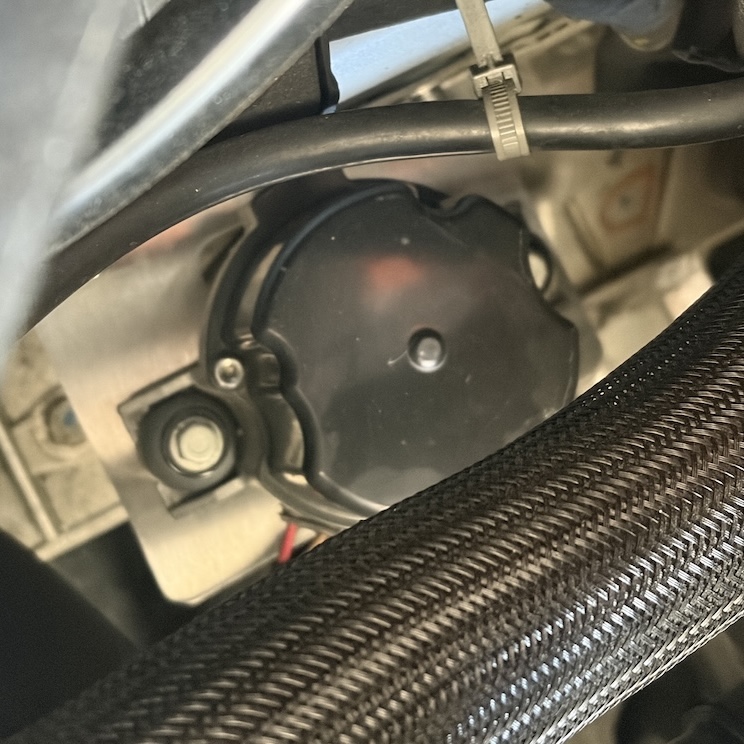
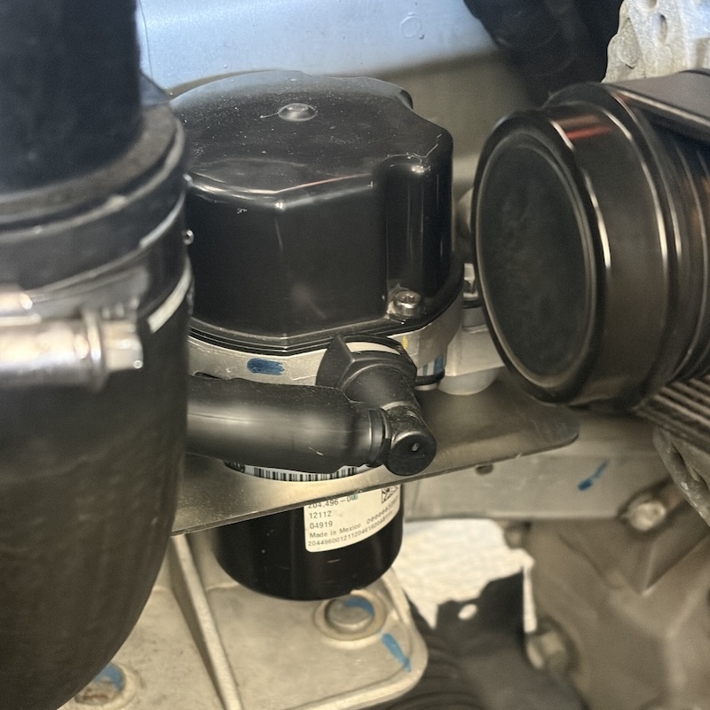
I then installed the bracket, sandwiching a small rubber washer between the bracket and the mounting surface. I also applied a small amount of blue thread locker to the M6 stainless-steel bolts before tightening them to specification. After that, I mounted the pump in its final location and tightened the mounting screws as well. Finally, I applied a dab of red paint marker to the bolts to indicate that they had been torqued to spec.
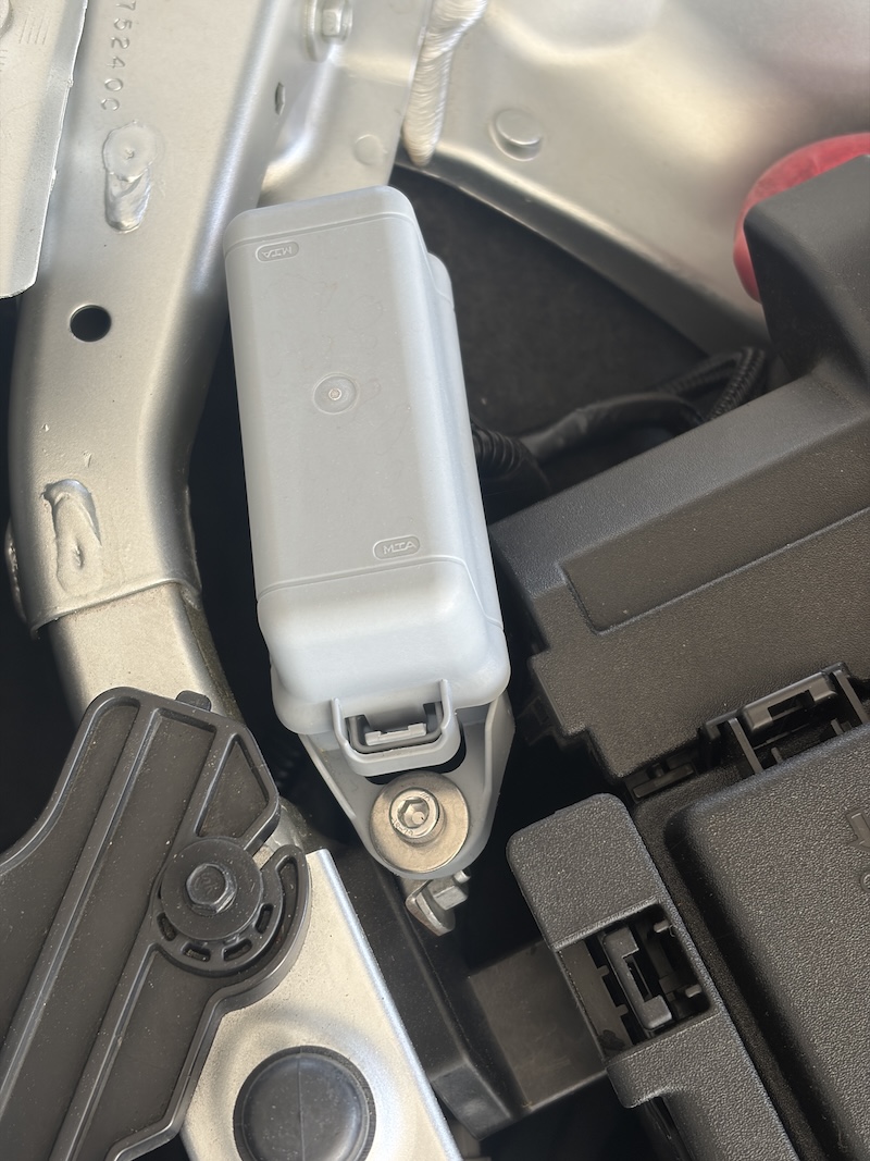

Next, I removed the OEM vacuum line from the mechanical pump. To disconnect it, you need to press the large button on the connector attached to the pump and pull the line upward. I then detached the line from the OEM vacuum sensor side as well. After inspecting the fittings, I found that the connector on the pump side could be reused with the electrical pump, since both pumps use the same receiver. At this point, it is important to install a vacuum line stop end on the mechanical pump, because the pump is still active and continues to generate vacuum. Leaving it open could allow dirt and debris to enter the engine. We will permanently disable the mechanical pump after verifying that the new system works correctly.
For the vacuum lines, I used a high-quality 3/8” silicone vacuum tube rated for 130 PSI. It blends well with the existing lines under the hood and fits nicely over the BOSCH vacuum sensor without requiring any adapters. I routed the line under the wiper cowl from the driver side to the passenger side, then alongside the coolant reservoir and underneath the fuse box. The exact length required for this route was 6 ft. I used thick heat shrink to shape the line similarly to the OEM vacuum lines and to prevent kinks around bends under vacuum. I also reused the connector from the OEM vacuum line and attached it to the electrical pump, since both pumps use the same fitting.
After cutting the line to the proper length, I mounted the second vacuum sensor inline between the pump and the OEM vacuum sensor attached to the brake booster, making sure that it was installed in the correct direction so that the internal check valve would function properly. Finally, I added aluminum heat shielding to the section of the vacuum line closest to the exhaust, similar to the OEM setup, before connecting everything together.
Testing in Stages
At this point, we have a working electrical vacuum pump in the system while the mechanical pump is disconnected from the vacuum circuit but still mechanically operating. Before permanently disabling the mechanical pump, we have to thoroughly test the new setup.
First, I switched the car into accessory mode, which immediately triggered the controller since the system did not have any vacuum. Then, while the car was still in ACC mode and the engine was off, I tested the brake pedal feel. The brakes felt completely normal, confirming that the electrical pump was providing brake assist even with the engine not running. I repeated this test for several cycles to make sure that the pump was turning on and off correctly and that there was no chattering due to incorrect hysteresis settings. Once I was satisfied with the bench testing, I moved on to road testing.
I kept the system in this configuration for approximately 1000 miles and tested it under a variety of conditions, including heavy traffic and long highway drives. During this process, I also monitored for any check-engine lights, since the OEM vacuum sensor is monitored by the engine control module. After I was fully satisfied with the reliability and performance of the system, I moved on to the final step: permanently disabling the mechanical pump.
Removing the Mechanical Pump
While there are fabricators who will modify your existing pump and adapt it into a block-off plate for the mechanical pump mounting location, I wanted to settle on a simpler approach. In this method, we keep the pump housing in place but remove the internals of the pump so that it is mechanically disconnected from the camshaft. However, simply removing the composite vane is not sufficient. The main shaft of the vacuum pump rides on a thin film of oil, and the vacuum generated by the pump helps maintain this lubrication. If the vane is removed without making any other modifications, the shaft may end up experiencing metal-to-metal contact, which would quickly destroy the pump housing. Therefore we have to decouple the mechanical pump from the camshaft by removing the coupling mechanism.
For this part, I directly followed the steps from terrainray. The only difference is that we are working with a rear-wheel-drive configuration, where the pump is located close to the driver-side firewall underneath the wiper cowl assembly, making the job considerably more difficult. This part of the process required a lot of planning and some extra ingenuity to create a few custom tools. I did not want to remove the wiper assembly, as it is a tedious task, so I wanted to complete the modification without taking it apart.
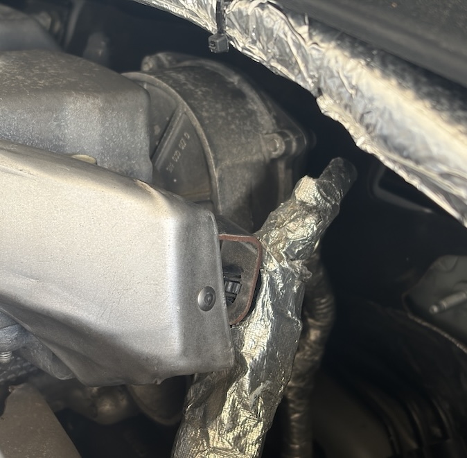
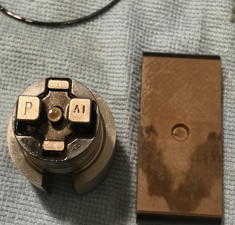
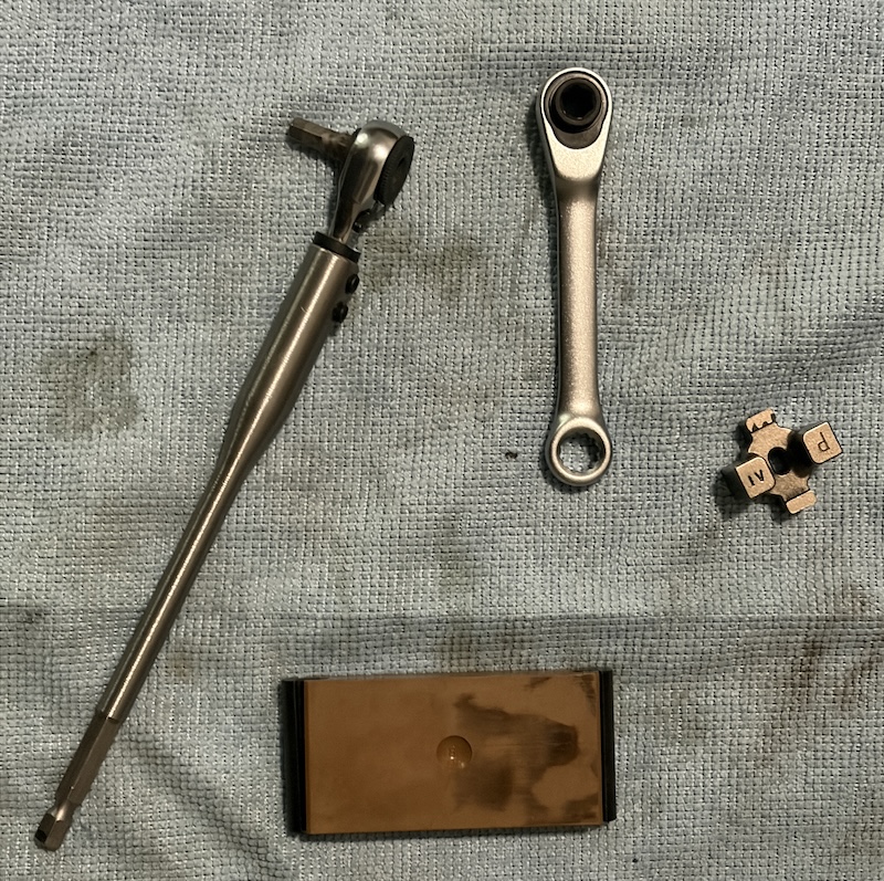
At this point, there is technically no going back unless you replace the OEM pump with another unit. Although it is possible to reinstall the removed components, I personally do not think that is a good idea. To avoid any concerns about how this modification would affect the engine’s oiling system, I decided to keep the main metal pump shaft inside the housing while disconnecting the pumping mechanism itself. The original pump housing provides a designed restriction for the oil flow, and changing that without fully understanding its implications did not seem worth the risk.
I performed the modification with the pump still mounted on the engine to minimize the chance of creating leaks at the pump gasket. This turned out to be by far the most difficult part of the entire project. The pump sits underneath the wiper cowl assembly, close to the firewall, and access to the rear cover bolts is extremely limited. In particular, removing the Torx T27 bolts was the hardest part of the job. To get enough clearance, I had to build my own extended miniature ratchet setup. Even then, there was barely enough room to work. The bolts needed a gentle amount of pressure from the back side while slowly turning them with the tiny ratchet through the limited space available. Removing all of the bolts required quite a bit of patience as they are prone to strip.
Before opening the pump, I stuffed a rag underneath the work area to catch any oil that might leak out. Fortunately, only a small amount of oil escaped. Once the rear cover was removed, I carefully saved the O-ring seal for reuse. The first component to come out was the composite vane assembly. After that, the rest of the pump internals could be pulled straight out of the housing.
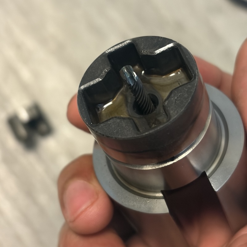
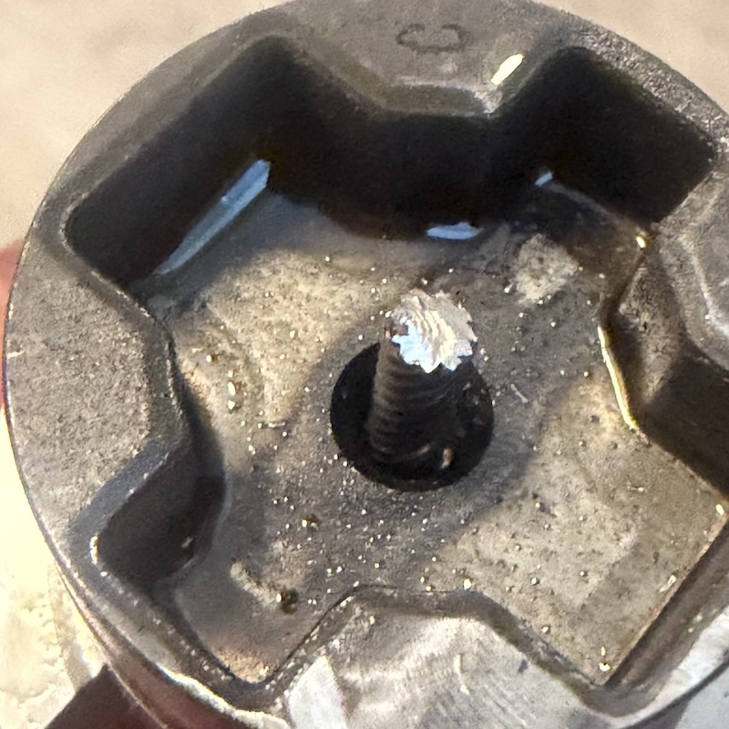
To disconnect the pump from the camshaft drive, I used a Dremel with a metal cut-off wheel to remove the retaining pin that holds the drive coupling in place. Since the drive is slotted, the retaining pin must be cut in the same direction as the slot. Care must be taken not to bend the pin while cutting, as doing so makes the process significantly more difficult. Once the cam-drive section had been separated, I thoroughly cleaned the modified assembly and applied a light coat of engine oil to the outside surfaces. The metal assembly, without the composite vane, was then reinstalled into the original housing. At this point, nothing should be contacting the camshaft directly, and the assembly should rotate freely without any unusual noises.
Before reinstalling the rear cover, I cleaned the O-ring and the mating surfaces. The cover was then bolted back into place using four new M6 x 16mm hex fasteners, instead of the original Torx T27 bolts. There is no need to overtighten these bolts. After completing the modification, I periodically inspected the area for oil leaks during the first few drives. Fortunately, everything remained dry, and the pump housing continued to stay exactly as intended without leaking oil.
Conclusion
With the mechanical vacuum pump now permanently disabled, the LTG engine no longer depends on a component that has become a known point of failure in the community. The electrical vacuum pump has been operating reliably and provides brake assist that is indistinguishable from the stock setup during normal driving. Since the entire system uses mostly OEM components, replacement parts are easy to source and the installation blends naturally with the rest of the engine bay.
Overall, I am very happy with how this project turned out. What initially started as a simple idea ended up becoming a much larger project involving research, prototyping, PCB design, fabrication, and many weekends of testing. From the initial planning stages to the final installation, the entire process took more than six months to complete. Although the conversion itself is fairly straightforward in principle, a significant amount of time went into selecting appropriate components, validating the control logic, designing the mounts, and ensuring that the system would survive the harsh automotive environment Hopefully, documenting the entire process and publishing all of the design files will be useful to others who are researching the same issue or considering similar solutions for their own projects.